The program describes the dawn of reciprocal space building and geometrical explanation of diffraction: how does different type of sample and detector moving scans reciprocal space - see figures
1 -
3. Correct accessible region in reciprocal space for both Bragg and Laue geometries could be calculated for any crystal with any normal orientation and for any plane of incidence - see figures
4 -
10. Formulas for calculation of this figures could be found in appendix
A. For visualization of accessible reciprocal nodes beam-passes could be plotted fig.
11. Also the program shows basis of reciprocal space mapping for 1-layer and 2-layered systems. The program is very dynamic in 3 dimensions - user can change many parameters (what does every control do is described as Hint).
The idea of building such program arises at X-TOP 2006 tutorial, where D.Lubbert tried to show such things, but there were only static pictures which were understandable only for people who already know all of it.
The program was shown with explanation at the conference in V.Novgorod (may 2007) and it had great success - most young scientists told that it was very interesting and understandable and even such well known people as Bushuev, Kutt, Punegov, Suvorov, Shulpina, Lomov etc. liked the program.
This program hopefully will help young scientists of the world to understand X-Ray diffraction better.
Final release of this program with some features improved and help file will be placed on this cite a little bit later. Maybe ready presentation will be made and placed here as well.
A Main formulas in Cartesian coordinates
For a given reciprocal point with vector
Q (
|Q| = Q < = 2 K) and given plane of incidence with its normal
P, incident beam
K0 could be found by solving equations:
| |
|
((Qy Pz- Py Qz)2+(Qz Px - Pz Qx)2+(Qy Px - Py Qx)2) K0x2 |
|
| |
| |
|
- Q2 (Qz Px Pz + Qy Px Py - Qx (Py2+Pz2)) K0x + |
|
| |
| |
|
Q4 (Py2+Pz2) /4 - K4 (Qy Pz - Py Qz)2 = 0 ; |
|
| | (1) |
|
|
K0y = |
- Pz Q2 /2 + (Px Qz - Pz Hx) K0x
Pz Hy - Py Hz
|
; |
| (2) |
|
K0z = |
- Py Q2 /2 + (Px Qy - Py Hx) K0x
Py Hz - Pz Hy
|
. |
| (3) |
Diffracted beam
Kh is then:
|
Khx = K0x + Qx ; Khy = K0y + Qy ; Khz = K0z + Qz . |
| (4) |
If considering simplified coordinate system, where vectors:
N = (0,0,N
z),
P = (0,P
y,0),
K0 = (K
0x,0,K
0z), equations (
1)-(
3) take the form:
|
(Qz2 + Qx2) K0x2 + Q2 Qx2 K0x +Q4 /4 + K4 Qz2 = 0 ; |
| (5) |
|
K0y = 0 ; K0z = ±(K2 - K0x2)1/2 . |
| (6) |
In described coordinate system equation for fundamentally accessible reciprocal points (a half of torus for Q
z > 0 on fig.
6, yellow surface on fig.
7 and green for Q
z > = 0 on fig.
8) takes the form (here and below
- 2 K < = Q
x < = 2 K and
- K < = Q
y < = K are set and Q
z is calculated):
|
Qz4 + 2 (Qx2 + Qy2 - 2 K2) Qz2 + (Qx2 +Qy2)2 - 4 K2 Qx2 = 0 . |
| (7) |
Only positive Q
z should be considered, because surface for Q
z < 0 is determined by equation K
0z=0 - it is described below.
Equation for surface, where
Kh is parallel to the crystal surface (K
hz = 0) is:
|
Qz4 + 2 (Qx2 - Qy2) Qz2 + (Qx2 +Qy2)2 - 4 K2 Qx2 = 0 . |
| (8) |
One solution of this equation is plotted in yellow in fig.
8 and the other in purple in fig.
7. Two other roots are negative and non-accessible due to the presence of the surface, described below.
Equation for surface, where
K0 is parallel to the crystal surface (K
0z = 0) is:
|
Qz2 = - Qx2 - Qy2 + 2 K |Qx| . |
| (9) |
The roots are shown in green in fig.
7 (Q
z > = 0) and in fig.
8 (Q
z < = 0).
Some figures:
|
Omega/2Theta
|
Omega
|
|
|
|
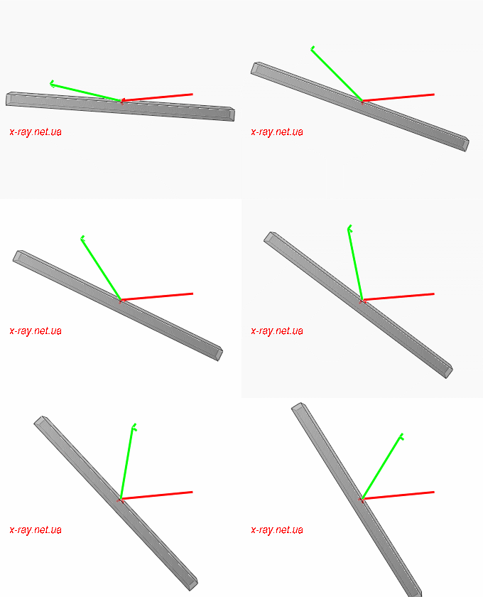
Figure 1: Moving of beams for Omega/2Theta scan. Incident beam K0 is red and diffracted Kh is green.
|
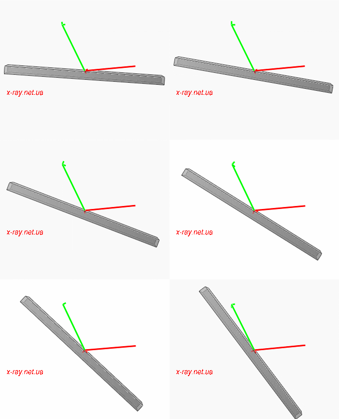
Figure 2: Moving of beams for Omega scan. Incident beam K0 is red and diffracted Kh is green.
|
|
2Theta
|
|
|
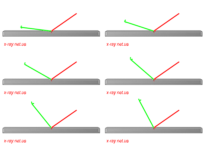
Figure 3: Moving of beams for 2Theta scan. Incident beam K0 is red and diffracted Kh is green.
|
|
Picture
|
Description
|

|
Figure 4: Plotted in some books accessible region for non-coplanar Bragg case. (218kb)
|

|
Figure 5: Possible ends of vector Kh is a sphere. Kh - green, K0 - red. (373kb)
|

|
Figure 6: All fundamentally accessible for current l reciprocal points lie inside the torus. (445kb)
|

|
Figure 7: Right accessible reciprocal region for Bragg geometry in general case. (539kb)
|

|
Figure 8: Right accessible reciprocal region for Laue geometry in general case. (842kb)
|
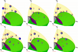
|
Figure 9: Right region (one quarter) for Bragg geometry for Si [001] crystal using structure factor. (214kb)
|

|
Figure 10: Right region for Bragg geometry for InAs [001] crystal using structure factor. (415kb)
|

|
Figure 11: Two possible beam-pathes for reaching 333 reciprocal node (blue point) for Si [001] crystal and incident beam belongs to (010) plane. Incident beam - red, diffracted - green. (75kb)
|
Download:
XVis v.1.1 (08.08.2008) - The program with some files needed for its correct work. Bug reports and question address to developers (E-mail is in "About" dialog of the program).
XVis sources The sources for Borland TurboC and Borland Builder 6. Compilation instructions in readme.txt.
Article about the program O. Yefanov, V. Kladko, M. Slobodyan, Yu. Polischuk // Journal of Applied Crystallography, 2008. V.41. Part 3. P.647-652. doi:10.1107/S0021889808008625
©
Yefanov O.M, scientific supervisor
Kladko V.P..
V. Lashkarev Institute of Semiconductor Physics, NAS of Ukraine

